Fluid flow analysis of fluid distribution in oil filling station.
Oil filling station is used to fill oil chambers to required capacity in specified time scale. It is then important to make flow reasonably even so time dependent filling will result in equal capacity of oil distributed between open chambers.
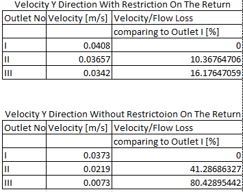
Two different settings have been compared in analysis to visualize the difference of flow distribution dependent on return pipe geometry. As expected flow is more evenly distributed when restriction is created on the return pipe which is important for equal filling of the set of chambers with oil. Tables below describe how important is that small difference in the geometry of the piping.
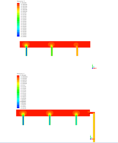
Values of the velocities are taken from the center of the flow of each outlets and are nodal values in analogous node position of each outlet.
Visualization of pressure drop makes it clear that small pressure drop will result in close to even velocity and flow rate so system version with restriction on the return outlet is worth considering.
Fluid parameters:
- dynamic viscosity: 55 Pa*s
- density 800 kg/m3
Analysis parameters:
- Navier Stokes solver for viscus and turbulent flow
- quad8 elements
- 0,01 convergence
- Fluid pressure 1,1e05 [Pa]
- Atmospheric pressure 1e05 [Pa]
Output information:
- velocity [m/s]
- pressure [Pa]
Velocity Magnitude Comparison. 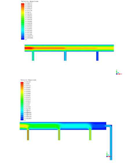
Pressure Comparison. 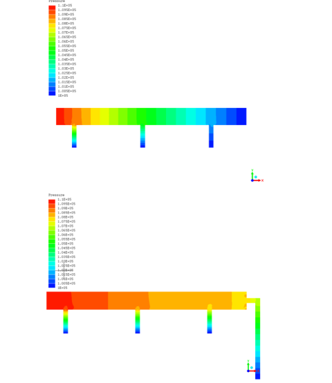
Velocity in X direction distribution. 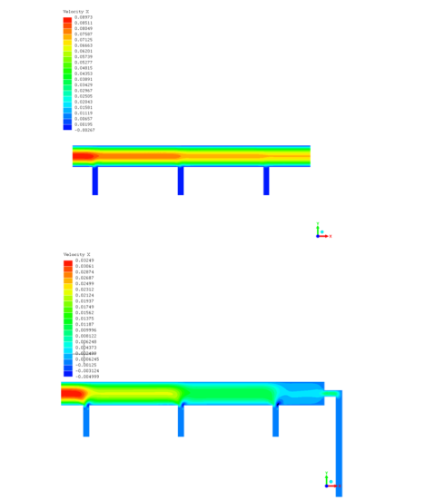
Velocity in Y direction distribution.